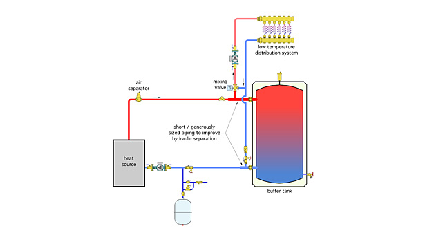
Schematic Chilled Water Buffer Tank Piping Diagram

Heatspring Magazine 2 Pipe Versus 4 Pipe Buffer Tank Configurations

Impovements To Ergomax Buffer Tanks
Alternate Methods To Pipe A Buffer Tank 2014 10 22 Plumbing And Mechanical
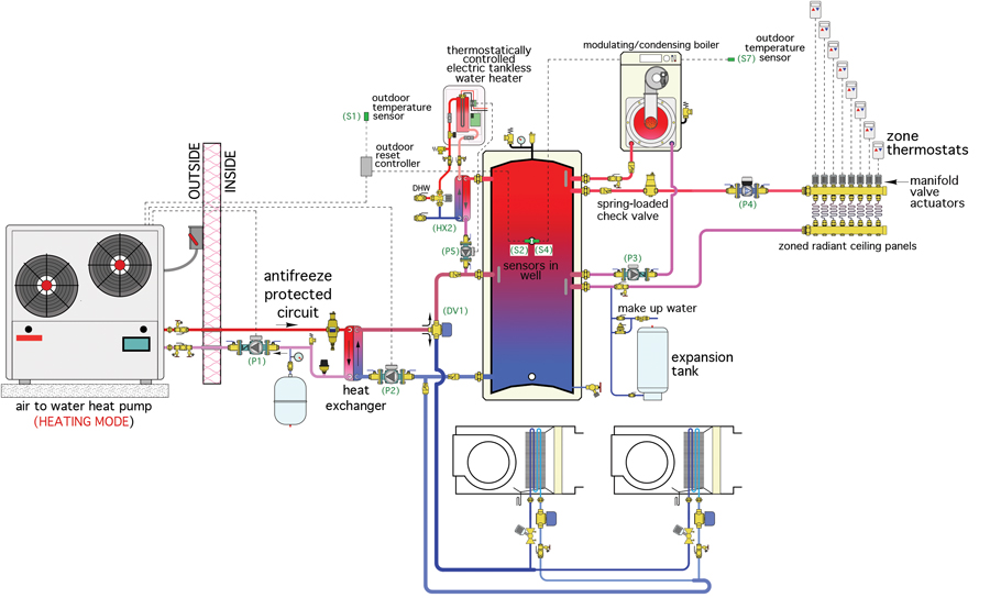
Heat Pump Plus Hpac Magazine
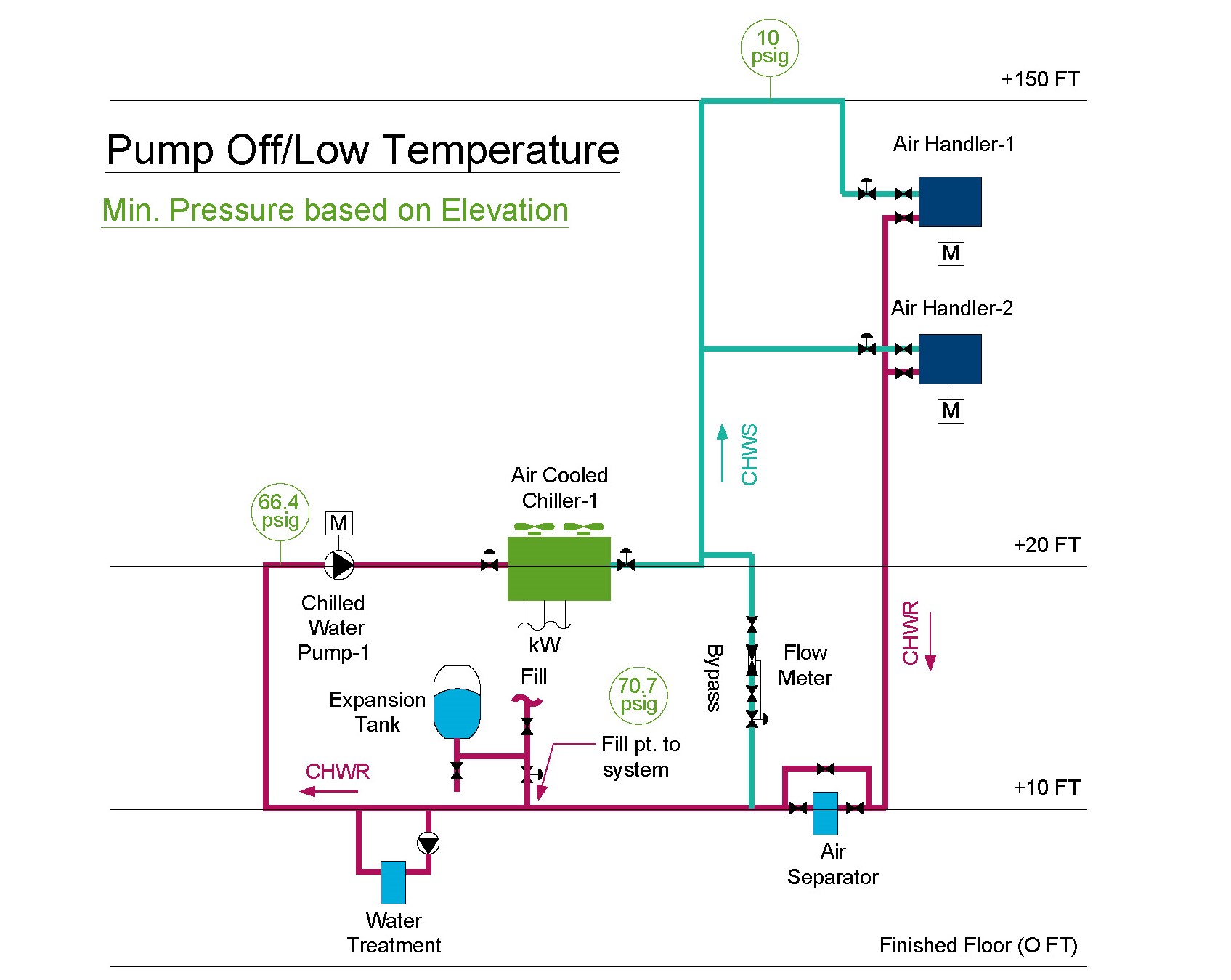
Expansion Tank Design Guide How To Size And Select An Expansion Tank For A Chilled Water System

Hot Water Storage Tank Piping Diagram Water Storage Tanks Reverse Osmosis Water Water Tank

Typical hvac chiller systems are between 3 to 6 gallons per ton.
Schematic chilled water buffer tank piping diagram.

Ecopower Principles

Spec Check Issue 1 Buffer Tanks Masterflow Solutions

Wheeler Tank Manufacturing Inc
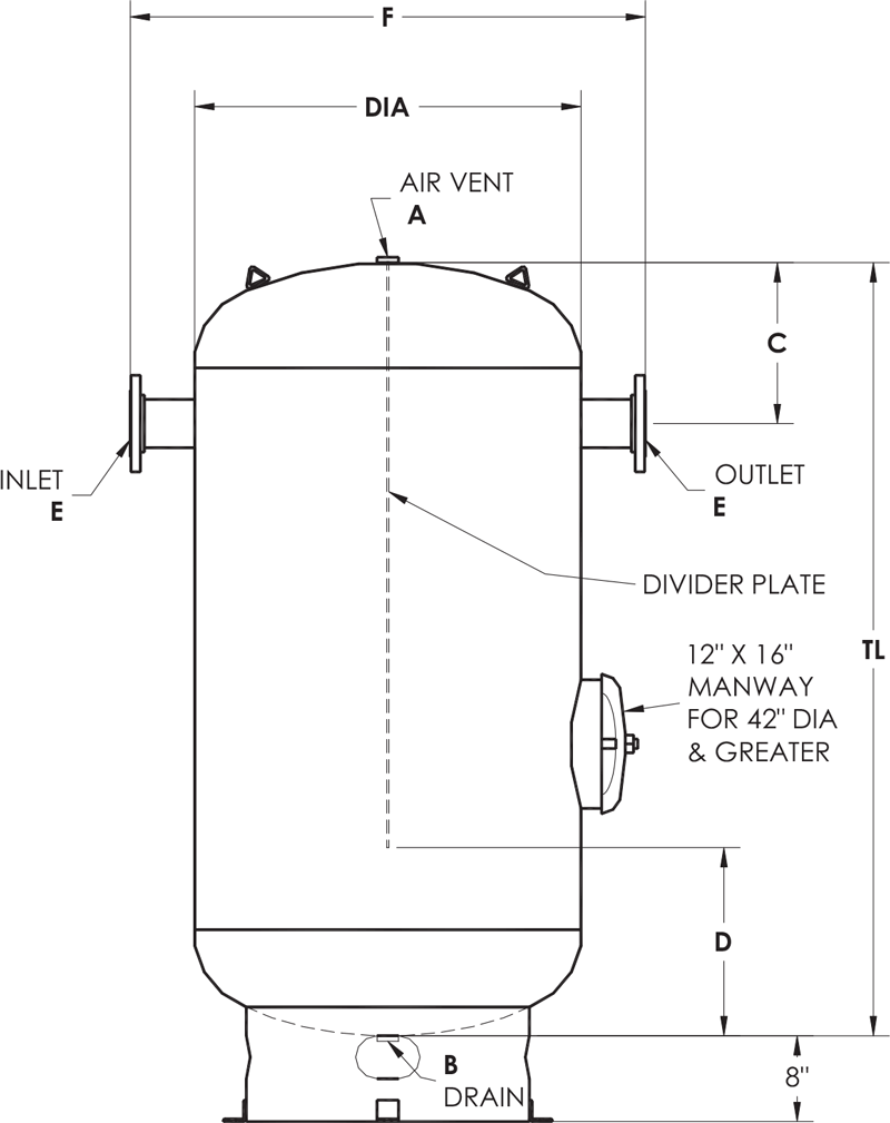
Asme Storage Tanks Elbi Of America Houston Tx
Source : pinterest.com
